standUP
Background
I completed this project as part of a mechanical engineering course on design and manufacturing. My goal was to create a stable surface that I could use to do both digital and written forms of work on while standing. What started as a simple design rapidly evolved in complexity as I attempted to avoid setting the shop on fire.
Process
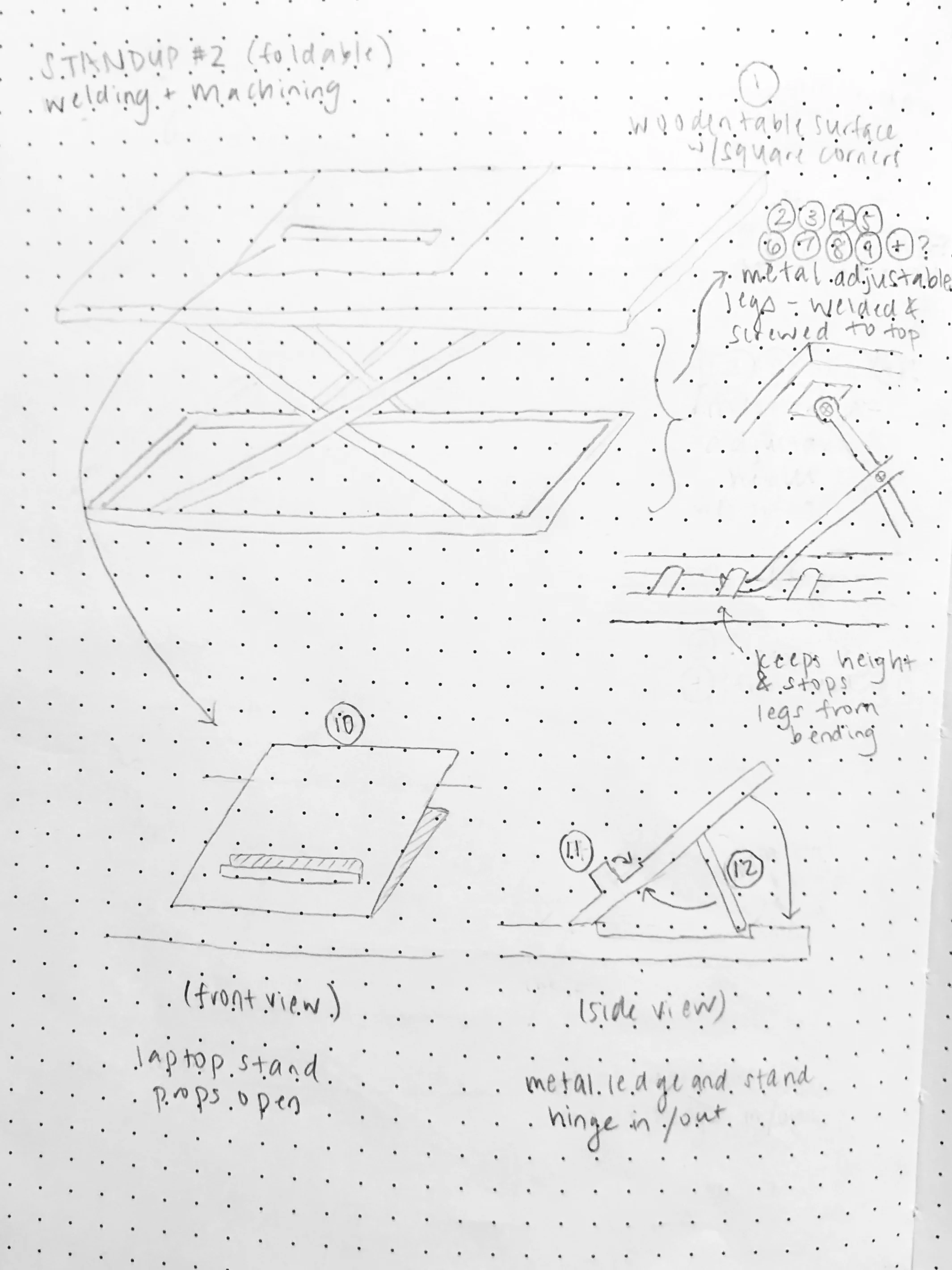
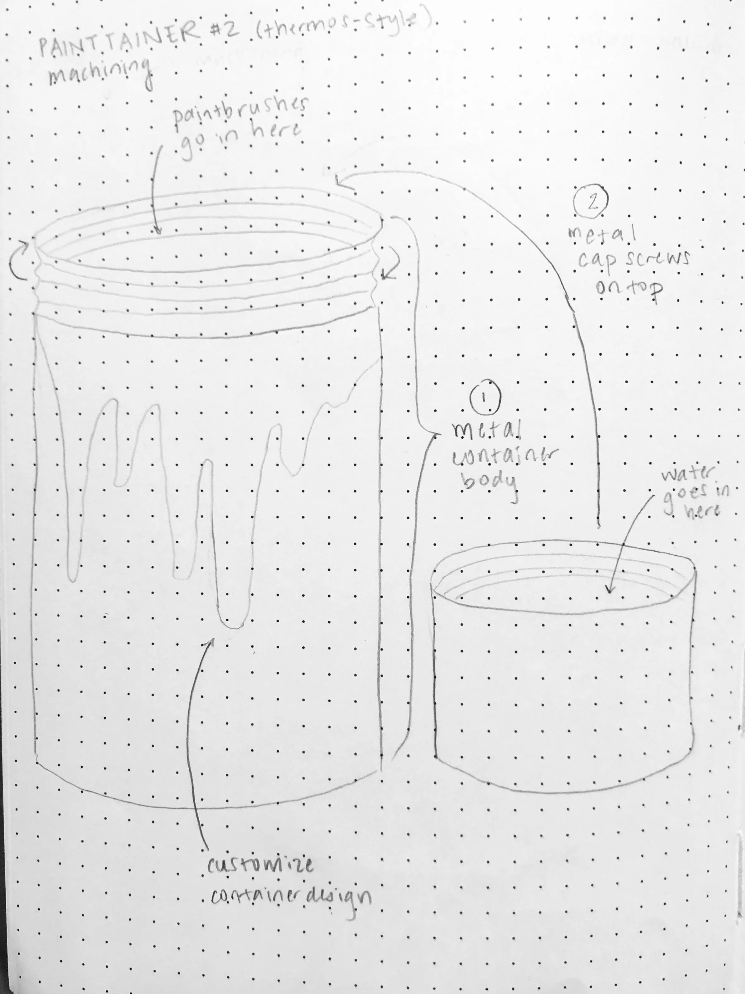
I began by coming up with several product stories that were meaningful to me and sketching out ideas for those products. For three ideas, I created more detailed sketches and scoped them in terms of time and cost.
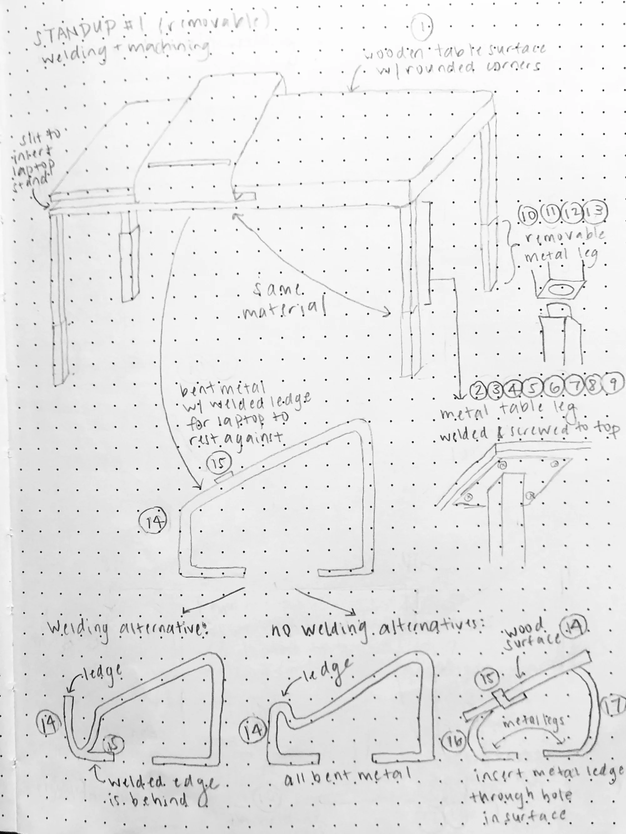


Of these, the one that was closest to my heart was standUP, which addressed my struggle with posture in this day and age of technology. Rather than being hunched over my laptop, phone, etc. all the time, I wanted to reclaim my posture by being able to stand while I worked.
I selected to move forward with standUP. My first step was to decrease my scope. Pivoting from my original product sketches, I took out all functionality that might afford removable or adjustable height. Working on the same table all the time and well out of my growth spurt, I really only needed one height for my product. In addition, I solved for dual work functionality by separating my table out into two tiers, which would enable laptop work on the upper table surface and paper work on the lower table surface.
The resulting design was a two-tiered, circular table topper made from a combination of wood and brass. I wanted my design to be as seamless as possible, which meant no visible outer attachments. I planned to assemble the table by brazing the tables legs to plates that would be screwed into the table underneath the table surfaces.
I tested my new design with a functional prototype made out of scrap pieces of wood. Seeing as it worked well, I then took my design to the next level by using Solidworks to create 3D CAD models of the parts and assembly, detailed drawings, and a bill of materials.

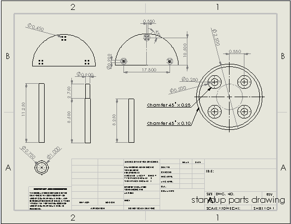
Engineering drawing in hand, I experimented with the different manufacturing processes that would be involved in making my product and generated an operations sequence. Repeatable parts and processes for each joint of my table ensured there would be plenty of room for practice and mastery.


At the same time, this was the pivotal moment when I realized that my design was not that simple. I had made both of the table legs that passed through the lower table surface two subtly different diameters, such that the lower table would sit on the larger diameter of the legs without needing any type of outer attachment. However, this meant that the lower table would have to be in place before brazing, which, being made of wood, was a fire hazard.
I was committed to keeping the seamlessness of the design, so I worked with the course assistants to ideate options for attaching the table legs to the plates without outer attachments. In the end, we landed upon creating custom internally threaded plugs that would be brazed into the table legs. These would then attach with a bolt that went through a countersunk hole in the plate and into the threads of the plug in the table leg.

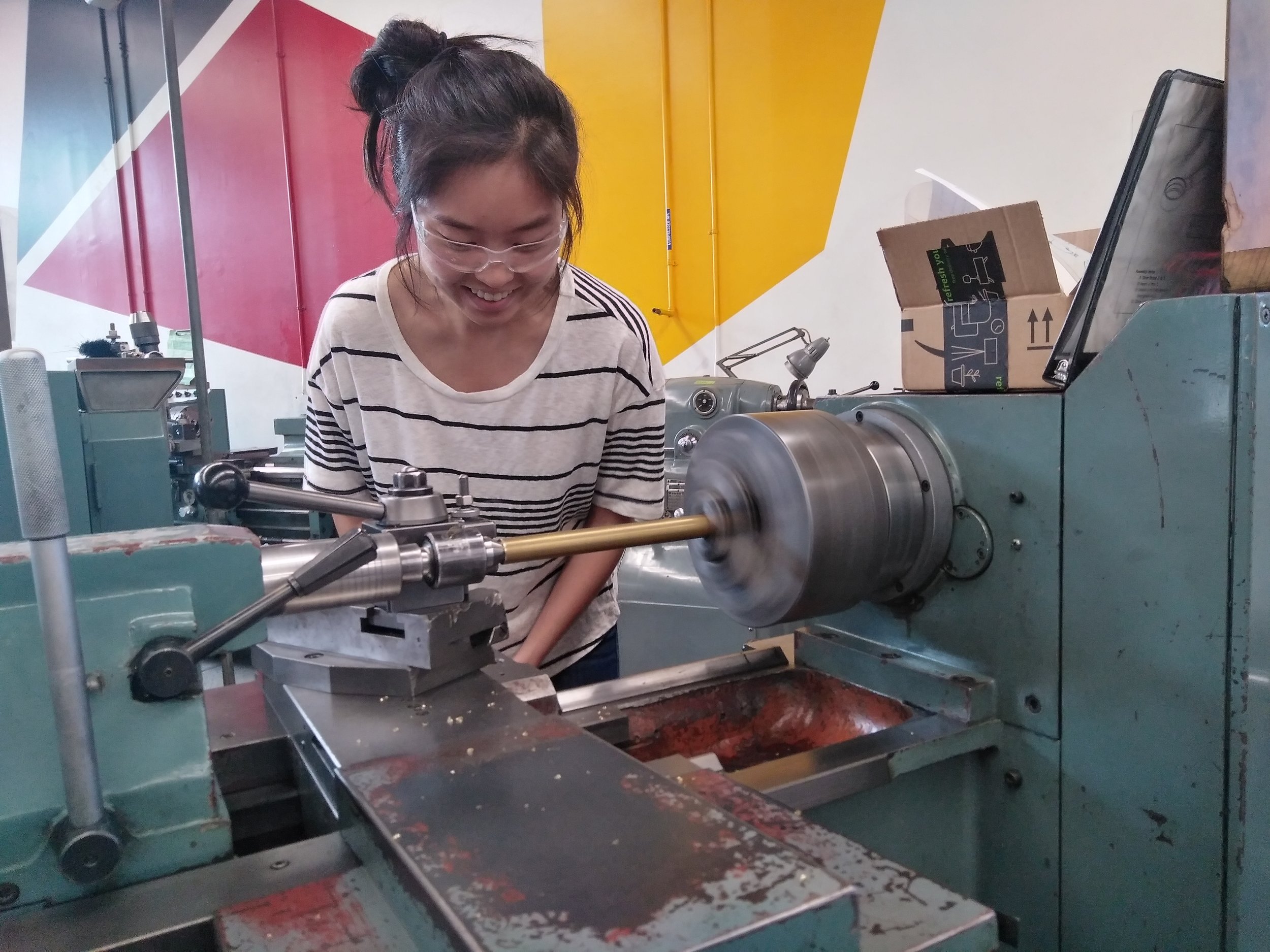
Switching to this attachment mechanism added significantly more time on the rotary mill. I made a time vs. cost payoff by choosing to make the plugs out of scrap material rather than increasing my budget to buy brass round stock. In addition, brazing the plugs into the inner diameter of the tube, even with the smallest torch tip and a generous length of silver filler, proved to be quite tricky to master.
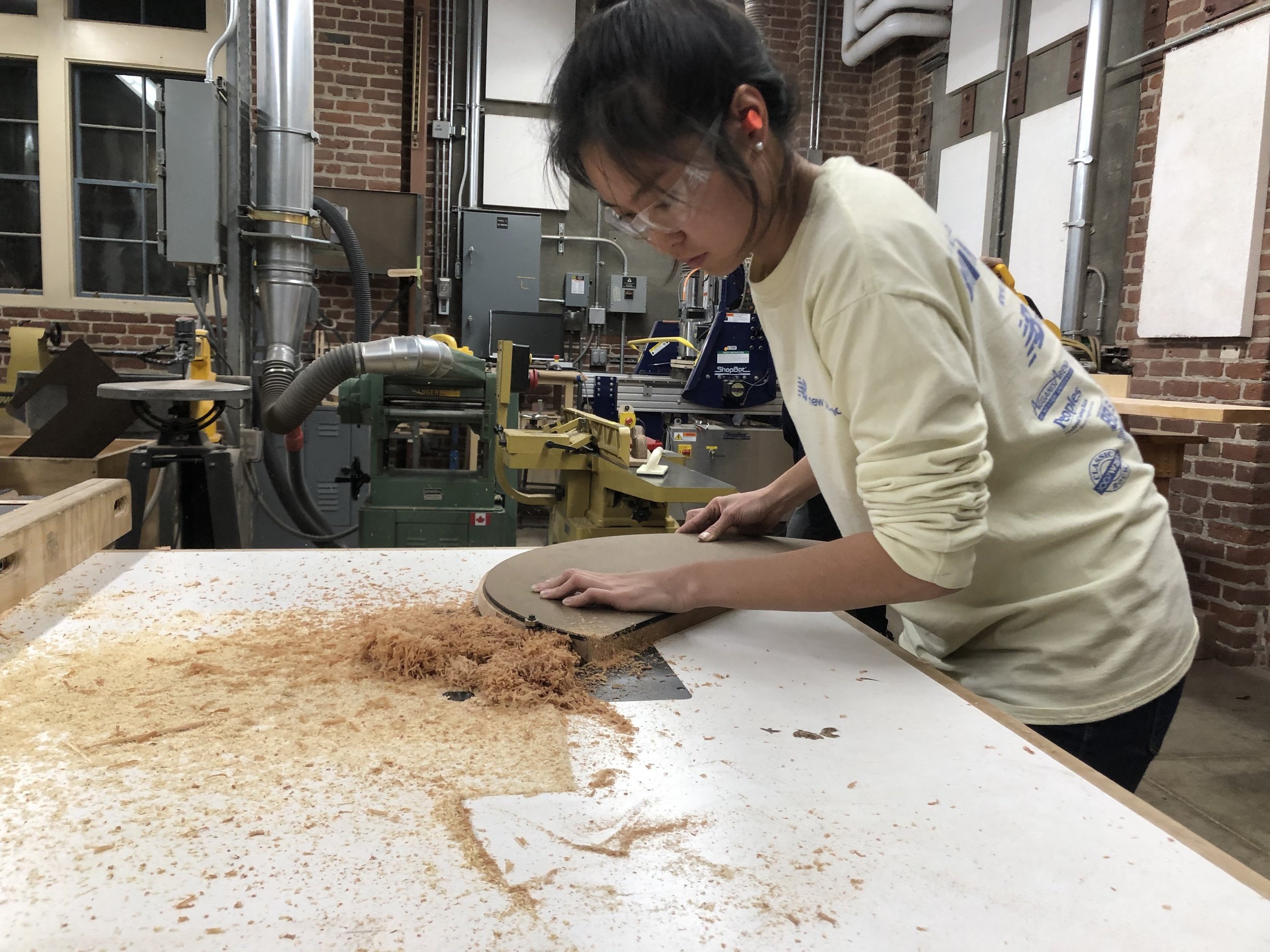
After undergoing the challenges of attaching the legs to the plates, the rest of the project went fairly smoothly. I spent the remainder of the quarter making, finishing, and assembling all parts of the table.
Outcome
I presented my product to the teaching staff and general public at the end-of-quarter showcase.


Length:
12 weeks
Materials:
Mahogany Wood
Brass
Processes:
Machining
Woodworking
Brazing
Other Tools:
Logbook
Solidworks
Other Skills:
Storytelling
Prototyping
Sketching